Glovebox Rebuild
- Model & Year: 95-01 7-Series, U.S.
- Expertise: Beginner
- Date: September 2015
- Updated: February 12, 2022
- Time Estimate: 3 hours
Tools Required
- 10mm Nut Driver or Socket
- Strut Compression Supplies
- Bench Vise with Wire (medium gauge) or
- Irwin Micro Quick Grip Clamp with M6 Star Clips
- Misc Hand Tools
Facilities Needed
- Garage or level surface
Parts Required
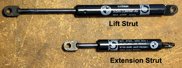
- (1) Glovebox Lift Strut (Damper): p/n 51 16 8 163 883, list: $57.41 (#11 above)
- (1) Glovebox Extension Strut: p/n 51 16 8 163 885, list $32.48 (#14 above)
- (1) Glovebox Handle (optional): $80-$100 used, $200 new (#2 above)
Getting Started
Does your E38's over-engineered glovebox fail to open after you pull the handle? When pulled forward, does it fail to remain extended? (Yes, the glovebox has two-way action: it opens and extends outward, for easy access to its contents from the driver seat.) If your glovebox does not smoothly operate as in the brief video below, it's time to replace both glovebox struts.
This would be a trivial job were it not for the length of the new extension strut, which makes it impossible to install without compressing it first (see Procedure below). The glovebox needs to be removed for access but don't worry, that's an easy task. There are also some finer points of glovebox installation and adjustment you should know.
If your glovebox suffers from a broken handle -- another common problem -- now is a good time to replace it. If you don't lock your glovebox, it's possible to purchase a used handle for under $100 (ex: on eBay). If you'd prefer a functioning lock, you'll have to purchase new through a dealer. However, new key-matched handles are about $200.
Procedure
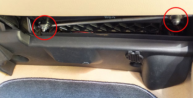
1) Underneath the glovebox, remove the plastic caps from both mounting points and release the two 10mm nuts that fasten the glovebox to its hangar rail. See image below (fastening element #9 in diagram A above).
2) Open glovebox and remove the three (3) screws on the left which connect the handle cover to the handle. Remove cover along with screws and spacers. See image below, panel A ( #7 and #8 in diagram A).
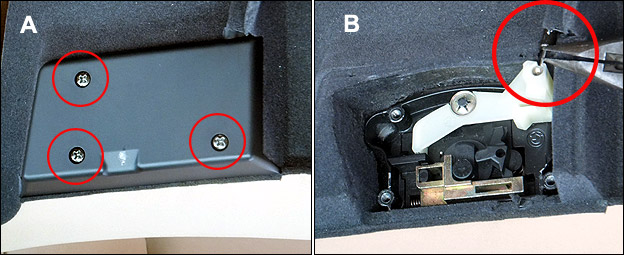
3) Using needle-nose pliers or similar tool, disconnect cable end from handle mechanism and extract cable from its channel on the lower left side of the glovebox. See image above, panel B.
The glovebox handle may fall out. Set aside. (If your handle is broken or damaged, replace it now.)
4) Using a pick tool, remove circlip holding lift strut to glovebox and pull strut end off glovebox pivot arm.
See image below, panel A.
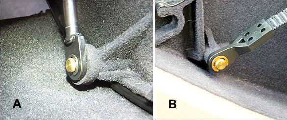
5) Similarly, remove circlip from right side extension strap and remove it from its pivot arm. See image above, panel B (see also #21 diagram A).
The glovebox will now come free. Support glovebox with one hand while pulling out, off its hangar rail. Set aside.
6) Remove the four (4) upper cover screws as shown below:
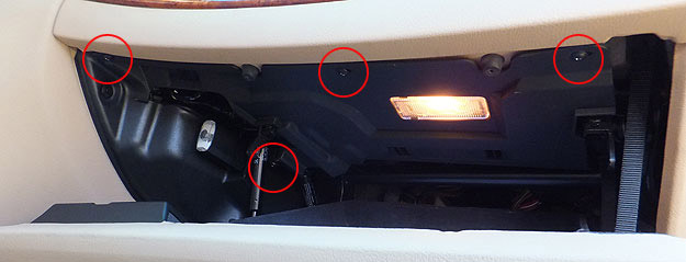
Drop front of cover and unplug connectors for glovebox light and light switch. Set cover aside.
7) Remove circlip from upper pivot of lift strut. Remove strut.
8) Release clips from each end of extension strut and remove extension strut from swing frame.
The clips are difficult to release. They hold the extension strut to its pivot arms with a tab, which acts like a circlip. Locate the tab and pry it away from each pivot arm. The clip may need to be tapped with a hammer in order to free the tab from the pivot groove. The new extension strut comes with new clips, so don't worry about damaging or even destroying the old clips.
New Strut Installation
Complicating strut installation is the length of the new extension strut: it is simply too long to fit onto the swing frame pivot arms. And the strut is too strong to compress by hand. Therefore, here's an improvised method for installation:
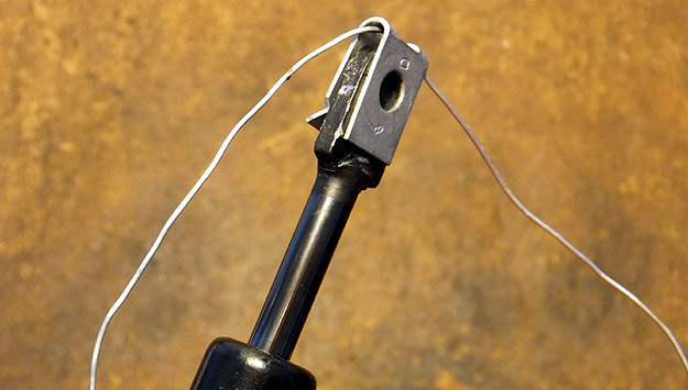
1) Thread medium gauge wire between the strut and clip on both ends. Leave enough wire to make at least two passes. See image below:
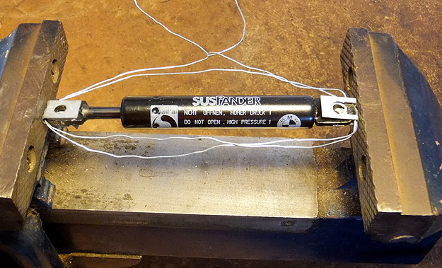
2) Place extension strut in a bench vise and compress approximately one inch. Draw wire tight by twisting with pliers or similar tool. This will hold strut in compressed state when removed from vise. See image below:
3) Remove compressed extension strut from vise and install onto glovebox swing frame.
Verify clip tabs are facing outward. The clips may be slightly displaced by the wire, so some effort may be needed to align both the clip opening and strut opening in order to fit the strut onto the pivot arms.
4) After installation, snip and remove wire from extension strut. Verify strut is secure on swing frame.
5) Install new lift strut onto its upper pivot arm and secure with circlip.
At this point, glovebox re-installation is reverse of removal, noting the following:
1) Handle Cover: It's very important the cable sheath remains outside the collar on the underside of the cover. Only the cable itself should extend through collar to handle mechanism. See image below:
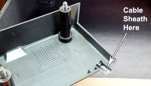
This will provide constant tension on the handle mechanism and return the handle to "closed" position after being released. A slight tug on the cable after cover installation will confirm cable sheath is correctly positioned. Then, tuck cable sheath into slot along left side of glovebox for a clean install.
2) Glovebox Adjustment: Place glovebox onto hangar rail but leave the fastening nuts loose, then close glovebox. Check the fit and closure. Adjust glovebox as necessary on rail before tightening nuts. Note fastening elements (#9 diagram A) not only provide for left/right adjustment but also fore/aft adjustment.
3) Handle Adjustment: With glovebox and handle in place, check tension on handle. Adjust cable screw if needed. See image below:
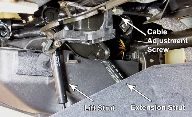
This screw adjusts the cable's sheath. Turning the screw back (towards front of car) applies more tension to handle, and vice versa. The other end of sheath must be correctly installed (from #1 above) for this to work. Typically, little or no cable adjustment will be needed.
When satisfied with complete installation, re-install upper cover as the last step.
Finally! Enjoy a fully functional glovebox!