Thrust Arm Bushings
- Model & Year: 97-03 5-Series (6 cylinder)
- Expertise: Intermediate
- Date: July 2014
- Updated:
- Time Estimate: 8-10 hours
Tools Required
- Powerbuilt Tool Kit #46 (rent from Advance Auto Parts, price: free, $180 deposit required)
- Metric nut drivers (7, 8, 10mm)
- 1/2" breaker bar with 3/4" and 7/8" sockets
- Hydraulic jack (optional)
- Basic hand tools and supplies
- Bentley or Haynes manual (optional)
Facilities Needed
- Garage (or solid surface)
Parts Required
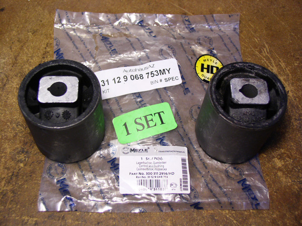
- Thrust Arm Bushings (of your choice; Meyle HD recommended, BMW p/n 31 12 9 068 753), for 6-cylinder models only. Price: $70-$100/pair.
Getting Started
Does your 5-series shake under braking? Does your steering wheel vibrate between 35-50mph? The most likely cause is failed thrust arm bushings on the front upper control arms - a common problem. Replacing them yourself will allow you to install a heavier duty bushing of your choice, which should result in a noticeable improvement in front-end feel and stability.
But there's a catch.
Suspension work requires special tools, which most people don't have. And the standard procedure for this job is to remove the control arms first, and then replace the bushings. This is time consuming.
BMW does offer a thrust bushing press tool set (p/n 83 30 0 491 942), but this set is best used with a hydraulic press. (Some have used this set with a large 3-jaw puller instead, but in my experience this type of puller is nearly impossible to keep centered.) Others have tried - and failed - to use a threaded rod thru the center opening of the bushing, because the opening's small diameter will not allow a rod of sufficient strength.
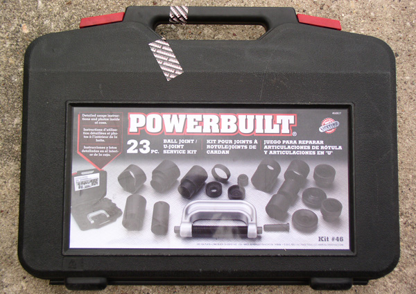
Fortunately, I have discovered that renting the Powerbuilt Tool Kit #46 (above, available from any Advance Auto Parts store for free, after $180 deposit) works well, and can be used with the control arm ball joints still attached to the car, thereby saving much time and trouble for the do-it-yourself mechanic.
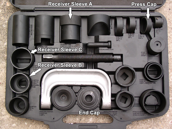
The tool kit contains press and receive sleeves of the correct size (for 6-cylinder models, may not fit 8-cylinder bushings) along with an industrial strength C-clamp press tool.
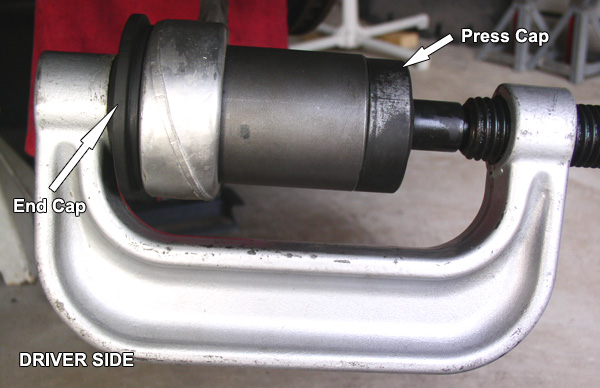
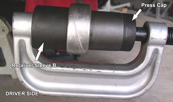
Use the diagram below to locate the needed press sleeves and caps (referenced in procedure):
Procedure
If you're doing this job for the first time, allow for about 4 hours per side of strenuous work. This job requires a lot of crawling around on the hard floor, so use work blankets as cushions. Prepare further by familiarizing yourself with the front upper control arm (thrust arm) procedures in either the Bentley or Haynes manual.
1) Highly elevate the front of your car safely on jack stands and remove front tires. (Never rely on jack alone!)
TIP: Slide your tires under the car (behind jack stands) to not only keep them out of the way but also provide an extra measure of lift safety.
2) Remove underside splash guard (belly pan). Using a 10mm nut driver, remove the (2) thrust bushing cover screws and remove both L and R covers. You will now see your quarry: the thrust arm bushings pressed into the front upper control arm:
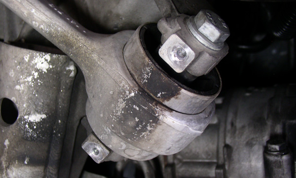
Above, notice how the stock bushing's fluid has leaked and stained the underside of the bushing and control arm. This confirms a failed bushing. (Meyle HD bushings are solid and contain no fluid.)
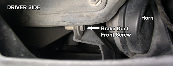
3) Remove both L and R brake cooling ducts, which are held in place by (3) 8mm screws. Two rear screws are visible in the wheel arch but the front screw is only accessible after removing the front grilles located next to each fog light (see image below). The grilles are held in place by two plastic rivets. These openings will make great viewing portals later when working on the bushings.
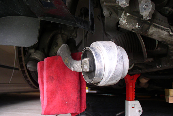
4) Using an 18mm (or 3/4") socket with 1/2" breaker bar, remove thrust bushing mounting bolt while counter-holding nut. Wiggle bolt free and drop control arm into plain view. Inspect.
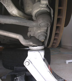
5) Place thick towel or rag over steering tie rod for protection. See image below:
You're now ready to begin working with the rented tools to press out the old bushings!
6) Remove old bushing as illustrated below. Use 7/8" socket and 1/2" breaker bar on C-clamp's jack screw. Grease jack screw before use.
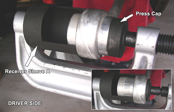
Begin by placing Press Cap on outside (front) of bushing, and Receiver Sleeve A on opposite end of C-clamp. A helping pair of hands will make this easier (or hold the C-clamp in place with your shoe while positioning the sleeve with your hands). Hand tighten jack screw to hold "the stack" in place.
Be sure jack screw is centered on Press Cap, and Cap is resting on bushing's metal outer sleeve. Also verify that Receiver is seated on control arm perimeter. Position Receiver opening so that it will allow viewing of bushing as it's pressed out (see inset image above).
PRESS TECHNIQUE
DRIVER SIDE: Start with breaker bar in vertical position (outside of front bumper) while sitting next to wheel arch, facing forward. Apply torque with both hands by pulling toward you. Re-position after each 1/6 turn. Stop after a few pulls to observe progress and verify position of the stack. Re-position stack as needed. It's not necessary to hold C-clamp while turning jack screw. If needed, allow C-clamp to rotate and rest on top of control arm.
PASSENGER SIDE: Start with breaker bar in vertical position (outside of front bumper) while sitting in front of bumper, facing rearward. Apply torque with both hands by pulling toward you. Re-position after each 1/6 turn. Stop after a few pulls to observe progress and verify position of the stack. Re-position stack as needed. Since control arm will tend to move inside with each bar pull (toward center of car), stabilize it with hydraulic jack as illustrated in image panel (A) below:
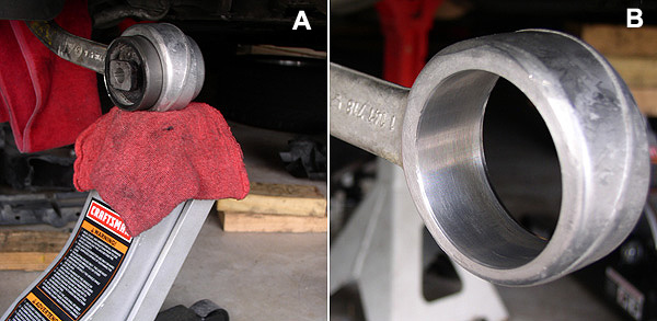
7) With old bushing removed, clean inside barrel of control arm with steel wool. See image panel (B) above. Take a much needed break to prepare for pressing the new bushing!
8) Prepare new bushing by cleaning and polishing outer surface with steel wool. This will help reduce the amount of force needed to press it in.
9) Position and seat new bushing in front of control arm barrel with bushing arrow mark pointing down the arm. See image below:
Twist the bushing as you seat it in the barrel to help start it. The bushing should remain in place when released.
10) Install new bushings with identical press technique specified in step 6. However different press tools must be used as specified below, because introducing the full length of new bushing into the stack limits the press tools which fit. Therefore, a three step process must be employed:
STEP 1: Begin with Press Cap and End Cap only (as shown below). The End Cap also provides maximum stability for starting the bushing. But the End Cap will only allow about 7/8" of press depth before interfering with bushing. Therefore, mark outer bushing sleeve at measured spot (use Magic Marker or similar, as seen below). DO NOT press beyond this depth.
Grease jack screw liberally. Screw will become warm to the touch from friction of applied torque. You will soon notice the greater force required to press in new bushings versus removing the old.
STEP 2: Once limiting press depth is achieved, swap End Cap for Receiver Sleeve B (as shown below). Although this Receiver's diameter is too small to receive the bushing, its purpose is to allow bushing to be pressed in another 3/8" (until bushing sleeve is flush with opposite end of control arm barrel) , which allows more jack screw thread for Step 3. Again, visually mark bushing sleeve at limiting press depth.
STEP 3: Once limiting press depth is achieved, swap Receiver Sleeve B for Receiver Sleeve C and End Cap (as shown below). This sleeve has the correct diameter to receive the new bushing. Verify correct placement of Receiver on control arm perimeter to allow bushing to emerge thru barrel. Press bushing thru until it is evenly positioned inside control arm barrel.
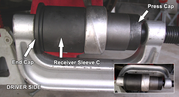
Note minimal thread available for jack screw in image above, due to the length of the stack. Allow C-clamp to rotate against top of driver-side control arm (bottom for passenger-side), in the direction of applied torque. See inset image above.
11) With both new bushings in, raise control arm back into its mounting bracket and secure with bolt. While counter-holding nut, snug-fit bolt only.
12) Final bolt torque should be applied with front suspension under load - a position under which it will spend most of its time. To simulate suspension load, use hydraulic jack under lower control arm ball joint. See image below. Raise jack until car almost lifts off jack stand.
13) With suspension under load, apply final torque to control arm bolt (81 ft-lbs). Officially, it's recommended to use a new self-locking nut (but not many do).
14) Re-install brake ducts and underside covers in reverse order. Re-install tires and lower car. You're done! A test drive should reveal your hard work has paid off.
While it's officially recommended to perform an alignment after suspension work, it's not especially required after this job unless your car no longer holds a lane.