Headlight Adjuster Replacement
- Model & Year: 01-03 5-Series
- Expertise: Intermediate
- Date: November 2013
- Updated: November 2014
- Time Estimate: 10-12 hours
Tools Required
- Metric sockets (8, 10mm)
- Long tweezers
- Long T15 torx driver (4" reach minimum)
- Dremel with cutting wheel or simliar tool
- Basic hand tools
- Bentley or Haynes manual (optional)
Facilities Needed
- Workbench
Parts Required
- Headlight Adjusters (various aftermarket sources), no BMW part number,
price: about $50/pair (plus shipping), 2 pair needed
Getting Started
Is there a '90's-era BMW that doesn't have failed headlight adjusters? These small but important parts are made from a plastic which literally disintegrates over time, causing the headlight beams to fall out of alignment, droop, and wiggle loosly in the housing. This is a drivability issue, making the car less than safe at night.
To verify failed adjusters simply grab the high or low beam's bulb socket and wiggle. If the combined reflector inside moves freely, you need new adjusters.
For those with 5-series '97-'00, good news: the headlight units have seperable lenses which allow easy access to the faulty adjusters. For these lights, BMW sells an adjuster repair kit (p/n 63 12 0 027 924).
However, 5-series '01-'03 headlights are sealed (probably to help prevent moisture build-up and discourage people from messing with the high voltage xenon lights) and use different adjusters. On the surface, it appears the only solution is to replace the entire headlight unit for around $1000 each thru the dealer network! Thankfully, the aftermarket has stepped in and reproduced the specific adjusters needed.
While You're In There:
Changing bulbs? Note that xenon light ballasts have a service life of only 5-6 years and therefore may not "fire" new bulbs. Furthermore, the light unit's internal projectors tend to deteriorate, reducing xenon light effectiveness. Replace these parts too for a more complete restoration (not possible for '03 headlights). My experience: Xenon Headlight Notes
While this DIY procedure is for '01-'03 headlight repair, some sections may apply to earlier units.
'01-'02 headlight units are known to have an adhesive which, if heated, will release the lens and allow access inside. But '03 units appear made with stronger adhesive which cannot be released by applying heat. But baking lights in the oven never appealed to me anyway.
Since the horizontal adjuster (low beam) is accessible thru the socket opening, the only problem is vertical (high beam) adjuster access. Like others, I feel the best approach is simply to cut an access hole in the top of the light unit for easy adjuster access. (Some have claimed to access the adjuster without cutting, thru the "Angel Eye" light socket, by pushing the light array from its mounting location. Be very careful if attempting this, so as not to damage the array.)
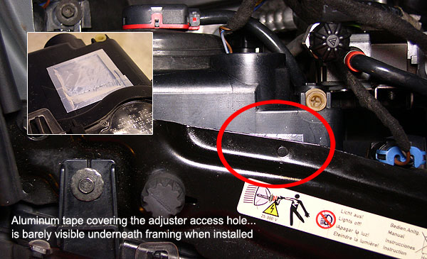
Once repaired, the access hole can be sealed by either glueing on a black plastic cover or simply by using aluminum tape. (Black electrical tape would look better but won't last long in the hot environment under the hood.) Worried about appearances? The cover or tape is barely visible once the light unit is re-installed (see image below). Using tape also allows easy future access if necessary.
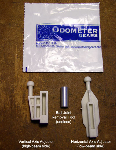
Since this is an unofficial repair, BMW does not offer replacement parts. You must purchase replacement adjusters thru aftermarket suppliers. An Internet search will easily locate vendors. I purchased adjusters manufactured by Odometer Gears. At the time of this writing, their website shows adjusters for $65/pair, but other vendors such as partsgeek.com sell the same Odometer-manufactured adjusters for $44.98/pair. You'll need two (2) pair.
Performing this repair requires time and patience. For the beginner, the first headlight unit will probably take 6-7 hours, while the other should take half as long. Afterwards, the required but neglected process of headlight alignment is just as tedious and will require several trial-and-error attempts over a few nights to fine tune. Of course you could pay a shop for this service, but after coming this far you may elect to complete the job yourself.
My notes on headlight alignment are at the end of the procedure below.
Procedure
This repair is not a minor undertaking. Prepare by familiarizing yourself with the headlight removal procedures in either the Bentley or Haynes manual (not illustrated below). Set aside an entire weekend of time. Place a towel over your workbench for protection against undue scratches to the lens.
1) Using a counter-clockwise 1/4 turn (as viewed from rear of light unit), remove all bulb sockets except HID socket. Unplug auto-leveler unit. Then, remove headlight unit by removing the four 8mm retaining screws. Move to workbench.
TIP: Corner bulb socket may be hard to reach. Pull light unit out a few inches for better access.
2) Using a counter-clockwise 1/4 turn, remove HID plug socket. Then, remove the three 8mm HID ballast retaining screws. Set ballast unit aside.
3) Carefully pull off the two rubber bellows covering the rear of both high and low beam openings. Again using a counter-clockwise 1/4 turn, remove the HID bulb retaining ring and remove HID bulb. Set aside.
4) Remove the three T15 torx screws holding the triangular auto-leveler unit. Disengage the leveler's arm from its receiver socket by moving the detached unit slightly toward the low beam while tilting it away, to angle its arm out the socket opening. Subtle movements and a bit of wiggle should free it. See image below.
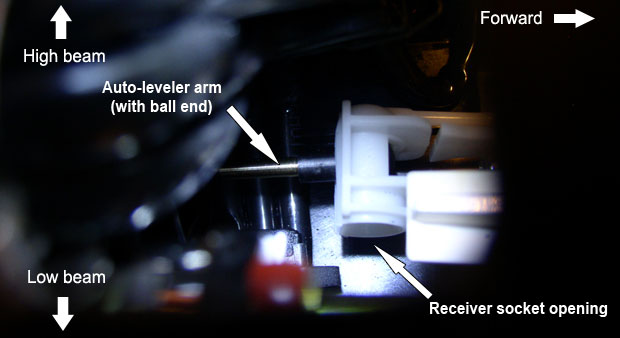
The headlight unit is now ready to receive the new adjusters.
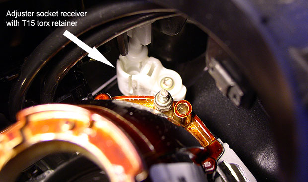
5) From workbench, remove low beam adjuster socket receiver thru low beam opening using long T15 torx driver. See image below. Extract with tweezers. The broken ball end of the old adjuster will probably be stuck inside the receiver.
On a workbench, extract the broken adjuster ball by pressing down on it with a small screwdriver or similar tool. It should crack into pieces. (The adjuster set sold by Odometer Gears comes with a "ball joint removal tool"...which I found totally useless. Discard.)
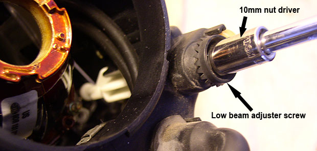
6) With 10mm nut driver on the low beam adjustment screw, back out what's left of the old low beam adjuster. See image below.
Remove broken adjuster peices from inside the light unit with tweezers. Turn unit up-side down and shake out remaining small pieces. Or, if available, blow out with compressed air.
7) Install new low beam adjuster in reverse order. Do not attach receiver to new adjuster ball end yet.
Begin by positioning adjuster to mate with adjuster screw threads. Note orientation of adjuster in above image. Turn adjuster screw while maneuvering adjuster - a delicate balancing process. Be patient. Tweezers aid with positioning.
Do not turn adjustment screw from 6mm hex wheel above adjuster screw. Use 10mm nut driver as illustrated above due to the high torque required to thread in the new adjuster.
Then using long T15 driver, re-attach receiver piece on reflector housing. Note orientation. Position reflector housing so as to obtain best access. Long tweezers will help position receiver. (DO NOT press ball end into receiver yet!)
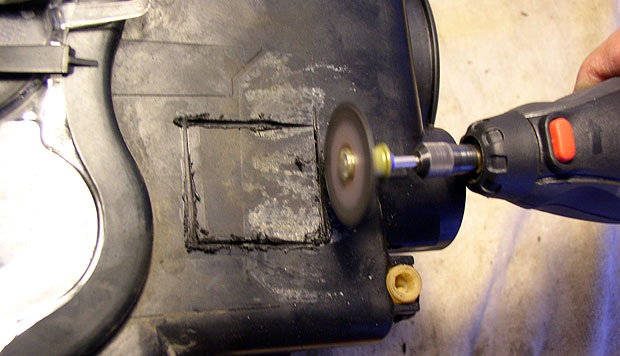
8) Moving on to the high beam side, use a Dremel with cutting wheel or similar tool to cut an approximate 1.6 inch square access hole above and to the side of the high beam adjuster (see image below). Do not penetrate deeply into the housing with your cutter.
10) Sighting either thru new access hole or thru halo light opening, use a long T15 torx to again remove the adjuster socket receiver and, as in step 5, clear the broken ball end from the joint. Then back out what's left of this adjuster by using a 10mm driver on the adjuster screw, as in step 6. Clear broken pieces from inside unit.
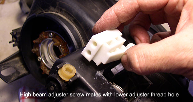
11) Install new high beam adjuster in reverse order but this time, couple the receiver to the new adjuster's ball before insering the new adjuster.
As in step 7, begin by positioning adjuster thru access hole (with mated receiver) into track to mate with adjuster screw threads. Note orientation in image below. This adjuster will mate with the lower of the two thread openings. Turn adjuster screw with 10mm driver while maneuvering adjuster by hand. This one is much easier to thread but will also require high torque.
12) Position the attached socket receiver (with attached T15 screw) close to its reflector mounting point by turning the adjuster screw. Then, reach thru either the halo light opening or access hole with long T15 driver to push receiver onto mounting location while threading screw. This is a delicate step, working in an area with obstructed visibility. Be patient. Use tweezers again to aid in positioning.
13) Finally, press low beam adjuster ball end into receiver socket, securing it to the housing. You're done!
Cover access hole with method of choice (plastic cover, aluminum tape, etc.) then reassemble light unit in reverse order. Re-mount the light unit and re-connect bulb sockets.
Headlight Alignment Notes
An overlooked aspect of this repair is the necessity of headlight alignment afterwards. If you choose to do this yourself, allow for a couple nights' fine-tuning before the job is complete. For those interested in technical accuracy there are online sources with frightening detail, such as Daniel Stern Lighting. For many this is too much information - and too much trouble. The ol' eyeball method works for me.
You'll need:
- 10mm socket with ratchet
- 6mm hex driver (for adjuster screws not accessible from rear)
- Flashlight
- Dark stretch of level pavement
- Garage door or large wall (to fine tune vertical adjustments)
Alignment work primarily centers on the low beam only (since both high and low beams are part of the same housing).
Parked on a dark stretch of pavement, turn on low beams. With engine off, you won't have to worry about a spinning cooling fan while you fumble in the dark. But don't linger too long as you'll run your battery down. With engine on, there's no need to worry about power but, watch out for that fan -- and belts.
Each beam should throw a distinct focus point. Are these visible? If not, wiggle the reflector housing by grabbing the high beam socket to discern where the beams are initially pointing. (Of course, avoid touching the high voltage low beam socket!) Cycling between high beams and low beams will further "illuminate" the initial situation.
Once you've located the horizontal focal direction of each light, begin turning the 10mm horizontal adjuster (located on the low beam-side) into alignment with the car's center line. If you must use the 6mm hex adjuster from above, it may skip gear teeth (which will sound like your new adjusters breaking!) and therefore require you to push the gear onto the adjuster screw while turning.
NOTE: The 10mm and 6mm adjustment points work in opposite ways! Viewed from rear of light unit: right turns on the horizontal 10mm adjuster pulls the housing in, while right turns on the same 6mm hex adjuster push out. Further note that drawing the right housing in, pulls the beam right, while doing the same on the left, pulls the beam left.
Once each low beam is in approximate alignment with the car's center line, you may begin to notice that each beam has a distinct up-tick on its right side, as illustrated in the image below:
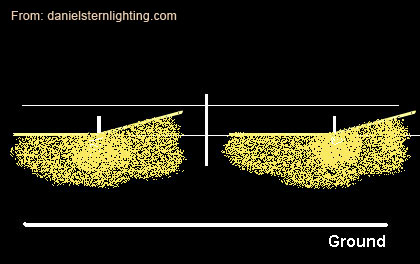
Apparently this is specific to the HID xenon lights and is meant to shine additional light onto the right side of the road. This, to me, just looks weird -- like a defect in the beam. Why this is necessary with xenons (and not regular bulbs) I'll never know and shows that, as a society, we're running out of things to worry about.
Anyway, you can now begin considering low beam vertical adjustment (distance). This may require a bit of trial and error to adjust correctly. You'll want an adjustment which is far enough ahead so you don't out-run the beam at speed but not too far ahead to blind on-coming traffic. I found switching to high beams helps with vertical adjustment, because high beams should point parallel to the road surface.
Using the vertical adjuster may affect the horizontal adjustment a bit, so some tweaking will be in order.
Finally, parked in front of your garage door with the low beams on will reveal if any tweaks are needed to bring both beams into identical vertical adjustment.